Posted By: Robert Nickels (ranickels) Posted: 12/21/2023 Vintage Ham Radio 12/21/2023 |
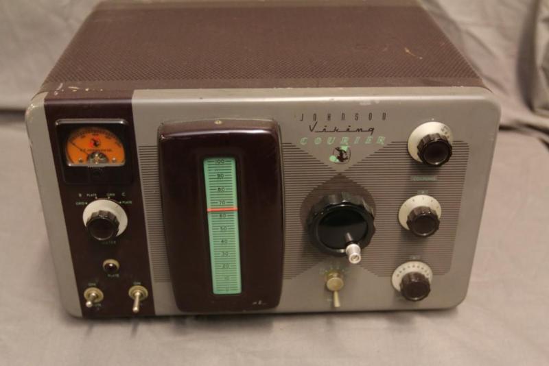
The Care and Feeding of the EF Johnson Courier amplifier |
|
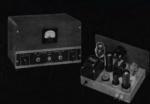
The EF Johnson "Courier" is a grid-driven amplifier using two 811A tubes. Switching is provided for operating in either class C for CW or as a class B linear amplifier for AM or SSB. Rated power is 500 watts input for CW, 500 watts PEP input for SSB, and 200 watts input for double-sideband AM with carrier. Since all amateur power levels were measured based on input to the final amplifier, that translated to 335mA and 130 mA respectively, with a plate voltage around 1500VDC. As was typical at the time, the output pi-network was capable of matching a wide range of loads from 18 to 600 ohms presenting an SWR of 3:1 or less. The grid input is broadly tuned and a 1400 ohm swamping resistor is permanently connected to provide a stable load for the exciter which would also have a wide range output network. In today's world where direct measurement of RF power is commonplace and some exciters require a 50 ohm load, a bit of care is encouraged when using the Courier amplifier. Especially when AM linear operation is desired, since AM peak power is four times that of the resting carrier. I'd overhauled the amplifier and knew it to be operational, but initial attempts to drive my Courier with a Multi Elmac A-54H were problematic, so I set the project aside until I had the time and proper test equipment to characterize the amplifier and exciter requirements.. The test setup is as follows: Bird 43 with 250 watt slug an 50 ohm dummy load with a sampler feeding a DSO on the output side. Excitation came from my TX-500 QRP portable that has very nice AM modulation and can be set for carrier levels up to 100% which in the AM mode translates to a measured 3.9W resting carrier (or ~12 watts PEP as would be expected for a 10 watt radio). To make things simple I set the TX-500 output to 100% and then used the grid drive control on the Courier to reduce it as needed. One problem I wasn't surprised to see is error in the Courier meter readings, especially the grid current meter. I can't remember if I checked or replaced the shunts, so for these tests I measure RF power directly using 50 and 250 watt slugs in the Bird, and confirmed by measuring RMS voltage across the 50 ohm dummy load. I tuned the Courier per the manual, using the plate meter for dip and adjusting the loading to achieve the desired output power. For reference, the height of the signal on the left screen corresponds to a 100 watt carrier with no modulation after setting the drive for 100 watts output on the Bird and the right screen shows speech modulation at that same output level:

(Note that these are relative indications of signal amplitude, measured through an RF sampler, not actual voltages) Critically there may be a tiny bit of flat-topping - it's hard to talk and push buttons at the same time and I think speech is a better indicator than two-tone. It may also be slightly under 100% but the important thing is that the peaks are generally rounded and clean. This 100 watt carrier (+50dBm) shows the Courier is providing an estimated 16dB of gain (based the 3.9 watt input signal (+36dBm) which has been attenuated a bit by detuning the grid). This is a very worthwhile improvement! I then peaked the grid drive which, with my 10 watts of drive produces right at 125 watts on the Bird. Again, it's just one capture but other observations proved that this is an acceptable power level, and is right in line with the manual spec of 200 watts input (which at 60% efficiency = 120 watts output)

Assuming the full +36dBm excitation is applied, the increase in output from 100 to 125 watts is slightly less than 1 dB. Thus 51-36 = 15dB Given that no one could hear a 1 or 2 dB difference, I'd tune the Courier to produce 100 watts output and give the amp a little breathing room.
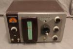
Next I returned to the A54H and found that it's resting carrier level is right at 10.8 watts (i.e. 40 watts PEP). This was measured both with the wattmeter and by directly measuring the RF signal level with the DSO (66VPP across 50 ohms or a bit over +40dBm). Not surprisingly this overdrives the Courier enough to pin the 250 watt slug. I reduced the drive by means of the grid tuning control to 250 watts on the Bird - here are the unmodulated (left) and modulated (right) waveforms with a 250 watt resting carrier:

This shows that the amplifier can't produce any positive peaks, only negative ones, and as a result carrier shift can be seen on the output meter (since the modulation is aysymmetrical). It also sounds lousy. Not what you want to put on the air! To confirm the results with the TX-500, I further detuned the grid tuning to produce a 100 watt carrier using the A54H and this is the result:

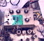
Again, this is through a sampler so the voltages shown are arbitrary, but correlated with 100 watts or +50dBm unmodulated carrier output. SO, a few conclusions: - using a wattmeter or other calibrated power meter to set the output power to 100 watts is probably the easiest and most reliable means of running the Courier as an AM linear. - make sure the meter shunt resistors are accurate if you're going to rely on the panel meters for proper tuning. Plate current of 130mA should correlate with 100-125 watts output. - detuning the Grid Tuning control does work to adjust the output power. The Courier manual mentions using "a power divider, reducing the exciter input, or as is done with the Ranger, with the Drive control". However it also discusses the interaction between the grid tuning and exciter output tuning. Clearly reducing the excitation power is the best method to use. - 100 watts of unmodulated carrier should be the goal - don't push it.- - when using a low power exciter (i.e. < 10 watts), the Courier with 400 watts PEP offers a significant benefit. But compared with the 40-50 watt carrier (160-200 watts PEP) output from an AF-67, AF-68, Ranger, etc - the fraction of an S-unit gained is insignificant and is not worth the effort. - that means a QRP exciter is ideal for AM - which is good news for those wanting to use their small SDR or other QRP radios on AM. 4 watts is all you need! Anything more is just going to be dissipated as heat - somewhere. - it also means that the Courier is a good match for entry-level AM transmitters using efficiency modulation such as controlled carrier modulation - providing output power can be controlled to within the limits of the amplifier. A Heathkit DX-40 with a 6146 PA was used to test this concept. Not surprisingly the CW output was 49 watts, and while the resting carrier is greatly reduced with this form of modulation, even the 6.5 watt carrier with no modulation drove the Courier to over 200 watts output. Detuning to reduce the output power is not a good way to reduce transmitter power, reducing the plate voltage would require modification so an external attenuator was used for testing. The output of the DX-40 was directly connected to a 50 ohm dummy load via a "tee" connector and a 6dB pad inserted in series with the drive to the Courier. This reduced the resting 38dBm carrier to about 32dBm or 1.6 watts, which resulted in an acceptably low resting carrier from the Courier of about 30 watts. Voice modulation easily produced 100+ watt peaks, taking advantage of the Courier's design to produce greater output with low duty cycle SSB signals, which efficiency modulation resembles. It's important to remember that the Courier was designed during the early days of SSB where exciters typically produced a few watts of power and relied on external high-gain grid-driven amplifiers to develop more usable amounts of RF power. Thus the Courier would have been an ideal mate for a Central Electronics 10A, 10B, or 20A, and could have been used with higher powered SSB transmitters since reducing the output power is a simple matter of turning down the mic gain. Given the other ways of producing a 100 watt AM signal and the cost of the Courier in comparison, I doubt that many purchased a Courier with the primary idea of using it as an AM linear (which was very uncommon anyhow). But it's possible to do so with attention to detail, gaining 3 S-units in the process. Addendum: Since it appeared that the Courier would be a good way to increase the power from a QRP transmitter, I proved that was indeed true using my class E transmitter. The voltage for the class D modulator is supplied by a DC-DC boost converter to provide 24 volt peaks and 9 watts output, but for this test I reduced the voltage to 15VDC which resulted in 4 watts of RF. The output power from a class E amplifer is proportional to drain voltage over a fairly wide range without reducing efficiency (80% in this case). That drive level resulted in a 125 watt resting carrier, so the voltage was further reduced to set the resting carrer power at 100 watts. The measured power from the class E exciter then was 3.3 watts, confirming previous results. Since that power level can be achieved with a $1 mosfet, this is an effective way to put a usable AM signal on the air. |
|
Latest Articles
Technical
Posted: 01/29/2025
Comments: 0 |
Pico Rx performance - Excellent performance on 630m WSPR
The Simple Pico Rx is my minimalist implementation of Jonathan Dawson's "Pico Rx" at 101things: https://github.com/dawsonjon/PicoRX In this basic form the receiver consists of a Quadrature Sampling Detector (QSD aka Tayloe) and the Pico2 MCU which handles all DSP functions. There are NO front-end filters, the only bandwidth limitation comes from the tracking filter... READ MORE |
Crystal Replacement
Posted: 08/226/2024
Comments: 0 |
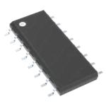
Making SMT "no lead" parts easier to use
SMT is the future - but how can we actually use parts without leads? ... READ MORE |
|
Crystal Replacement
Posted: 02/38/2024
Comments: 0 |
How good can a crummy receiver be?
Hundreds of different simple SDR receivers have been designed around Dan Tayloe's Quadrature Sampling Detector or QSD. Mine add nothing to the state of the art, and in fact subtract things, as I like minimalist solutions and the QSD is right in that sweet spot. Following the evolution of Tayloe's design I delete the resistors in series with the sample lines for inst... READ MORE |
Technical
Posted: 02/37/2024
Comments: 0 |
What's in a number (3253)?
The FST3253 dual four-to-one mux/demux IC has long been used as a "Tayloe Detector" or QSD (and QSE) in low-cost SDRs. They provide incredible performance for such a simple circuit, converting RF to baseband IQ with low loss and the ultimate in simplicity. Unfortunately the original FST3253 part has become obsolete and while substitutes are available, this is where the... READ MORE |
Vintage Ham Radio
Posted: 02/32/2024
Comments: 0 |
The Stancor 10P Transmitter
There weren't really many commercial transmitters in the 1930s as most hams built their own. But many of the ones that were offered came from the transformer companies who had two chances to profit. First, from those who would buy the kit, and two, from those would would see it in the (free) booklets the companies provided to their distributors who would then sell the iron to ham... READ MORE |
Vintage Ham Radio
Posted: 12/355/2023
Comments: 0 |
The Care and Feeding of the EF Johnson Courier amplifier
The EF Johnson "Courier" is a grid-driven amplifier using two 811A tubes. Switching is provided for operating in either class C for CW or as a class B linear amplifier for AM or SSB. Rated power is 500 watts input for CW, 500 watts PEP input for SSB, and 200 watts input for double-sideband AM with carrier. Since all amateur power levels were meas... READ MORE |
Historic
Posted: 11/329/2023
Comments: 0 |
TV Duplexer
Some things are interesting, even if totally useless nowadays. Such is the case with the Philco 426-3034 Crossover Kit for UHF TV. What the heck is that? Well, back in the late 50s, UHF television stations operating on channels 14-83 started to appear in many areas of the US where viewers had a VHF-only TV antenna, and in many cases an externa UHF converter was... READ MORE |
Crystal Replacement
Posted: 11/327/2023
Comments: 0 |
Replacing failed crystals
For decades, quartz crystals were used everywhere a stable frequency source was needed, even in some applications that depended on overtone (harmonic) behavior into the VHF range. These crystals were less stable and more dependent on circuit parameters that fundamental types and thus more problematic. Such was the case with the 94 MHz crystal in the 2 meter converter ... READ MORE |
Historic
Posted: 11/315/2023
Comments: 0 |
My Own Ham Radio Story by W9RAN
Everyone has a story of how they got involved in ham radio - this is mine. It started much earlier, including receiving a Knight Kit Span Master shortwave radio for Christmas in about 1963, at age 12. I'll never forget the night my dad and I finished building it and I wanted to try it out. It came with a 50 ft. antenna which was still coiled up - but ... READ MORE |

Technical
Posted: 09/267/2023
Comments: 0 |
Hot to simulate vacuum tubes in LTSpice
LTSice is a powerful simulation tool that is provided free by Linear Technology Corp. It comes with a complete library of passive and common analog solid-state components but if you want to use it to simulate vacuum tubes, it doesen't work as-is. Even though triode and pentode symbols can be found in the "Misc" folder, they are just schematic symbols and... READ MORE |