
Posted By: Robert Nickels (ranickels) Posted: 03/03/2022 Technical 03/03/2022 |
Some tips on the Johnson Pacemakeraka "Painmaker" |
|
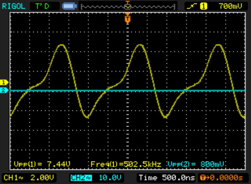
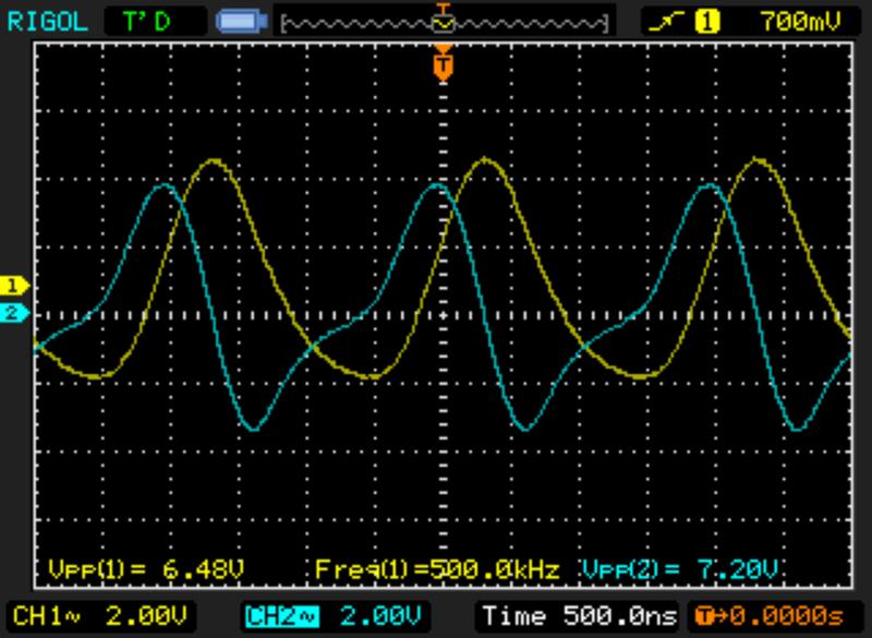
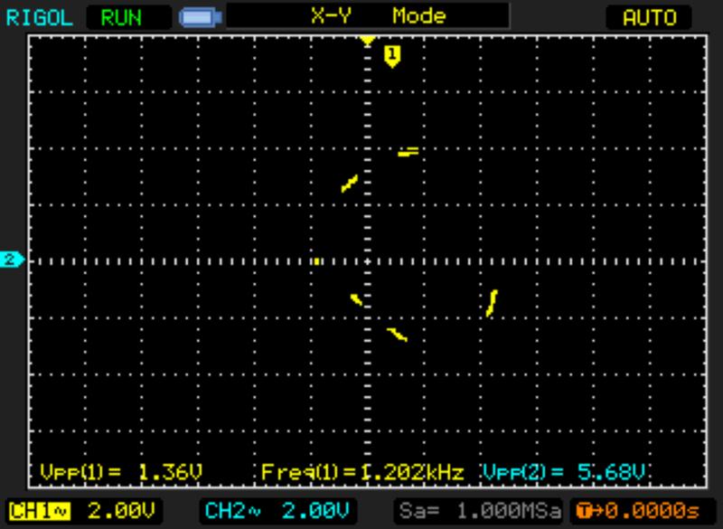
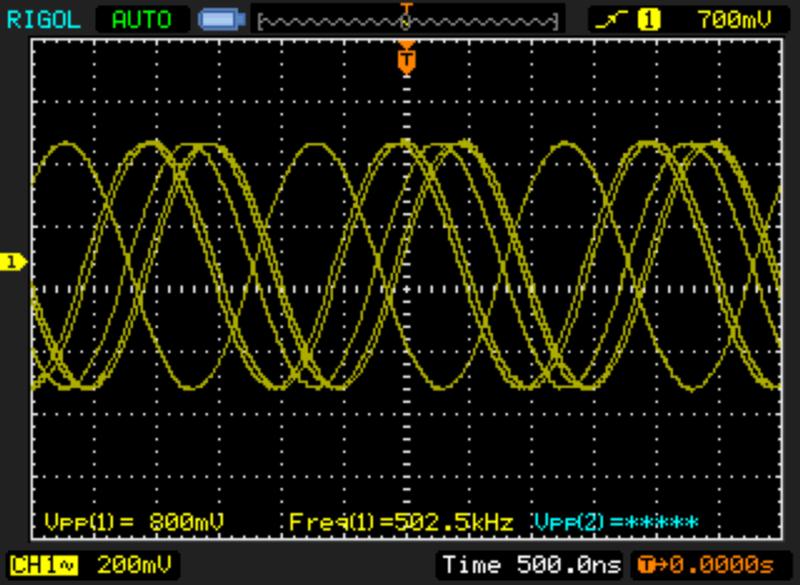
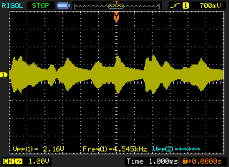
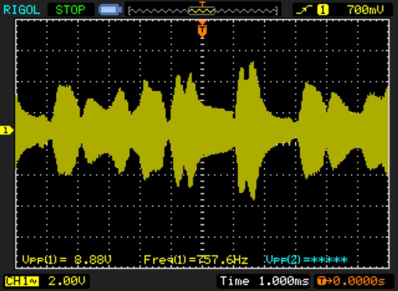
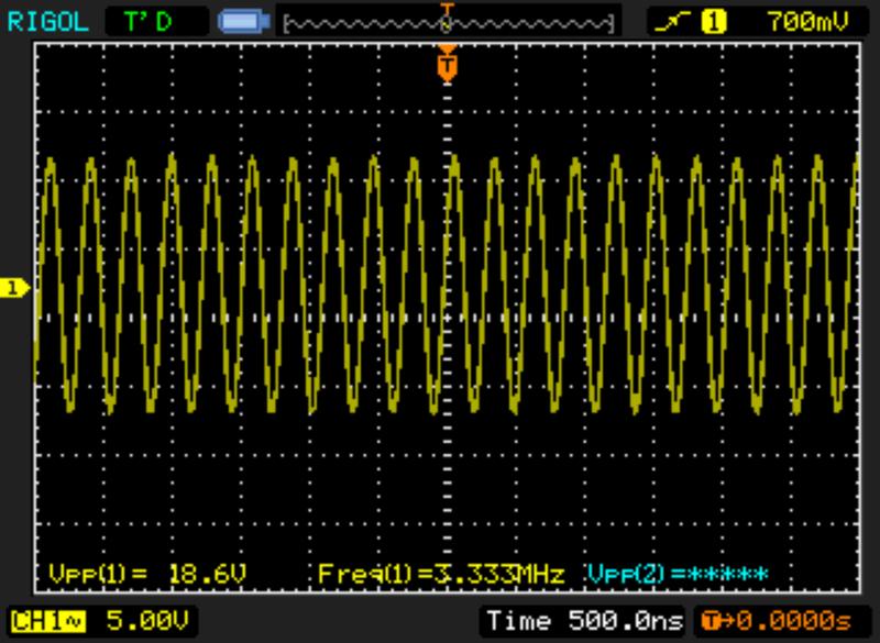
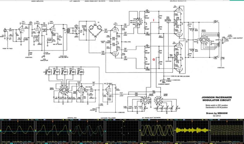
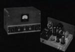
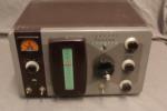
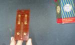
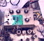
It's pretty well accepted that the Pacemaker was not EF Johnson's finest effort. In fact it was the first of several failed attempts by the King of the AM Transmitters to make the transition to SSB. In the end, it was the rise of CB popularity that kept the company viable, along with its component business, while their ham business gradually faced away. After the CB boom ended the company re-invented itself yet again as a provider of commercial trunked land-mobile equipment, which it remains today under the ownership of JVCKENWOOD. The Viking brand survives, but the "Viking Man" logo does not... The Pacemaker is a phasing SSB transmitter which would have been a lot better if Johnson had followed the Norgaard double-conversion approach used by Central Electronics, Hallicrafters, Lakeshore, and others with success. Instead, like the B&W and Heathkit SSB adapters the Pacemaker generated it's SSB signal on different frequencies for each band, but unlike those others it was not on the operating frequency. The Pacemaker VFO tunes from 3 to 3.5 MHz (or up to 4.7 MHz on some bands) and this is mixed with the SSB signal to generate the desired operating frequency. And therein lies the fatal flaw of the Pacemaker design. Take 80 meters for example, you want to operate on 3850 kHz. The SSB generator uses a 500 kHz crystal that is mixed with 3.350 from the VFO to produce 3.850 that is amplified and sent to the antenna. The low-level tuned circuits are tracked with the VFO just like in a receiver but the driver tuning is not - so if you accidentally adjust it to the wrong peak, you'll be sending the 3.350 VFO signal out to the antenna instead (the tuned circuits have a wide enough range for this to happen). Of course the resulting signal would be illegal and would not be capable of modulation since the audio signal was left behind. There are other flaws but you get the picture. EFJ knew about this and cautioned users in the manual, but it would have been nicer if they'd designed the transmitter to preclude these problems. I recently re-learned this when my Pacemaker lost output on 80 meters and indeed was outputting the VFO signal. After several hours of frustration and the use of language not suitable for the air, I bumped one of the carrier balance controls and saw the waveform on the scope change. A good sold rap with a screwdriver handle confirmed that an intermitted pot was lousing-up the balanced modulator and preventing proper mixing from taking place, with the result that the VFO signal was all that was present. Some manufacturers provide more detailed troubleshooting information than others, but EFJ was not bothered to include much of anything in the Pacemaker manual, saying that it was too complicated and too many things could go wrong. I'd say they were right about that but it's still a cop-out. The normal voltage and resistance charts aren't much help when you need to know if signal levels are as they should be, so while I was at it I made some of my own. Lee Craner WB6SSW aka Emmits Fixit Shop has done an outstanding job of redrawing the highly convoluted Johnson schematic to make it much easier to understand and use, and I highly recommend anyone who decided to tackle restoration of a Pain...I mean Pacemaker to read every word he's written at the link above. I've taken the liberty of adding my waveforms to his balanced modulator breakout schematic for future reference. The I and Q waveforms aren't perfect which is why the Pacemaker isn't capable of making the best SSB signal on the planet, but it's good enough for casual use on vintage SSB nets and such. An SDR with a spectrum/waterfall display is a vastly superior tool for adjusting the RF phasing coils on each band. I also made a couple of measurements of signals in the amplifier chain, although it's impossible to do so without loading the grid signal. But some data is better than none. The mixer output is only a volt or two peak-to-peak with modulation and the input from the bal mod is about 1 VPP with the carrier fully unbalanced, and a bit under 10VPP at the driver grid. The remaining tracked amplfiers take this up to the level needed to drive the 6146 PA. Note that the two RF phased signals are present at all times but everything from the balanced modulator on is keyed and subject to the carrier level settings. A word of caution about working on the Pacemaker. Aside from the usual precautions around high voltage, there are two neutralized stages - the 6146 PA and the 6CL6 Driver, and the neutralization capacitor for the driver is mounted on an insulator with it's shaft protruding through the side of the chassis and high voltage is present! I put several layers of kapton tape over it to guard against accidental contact when the chassis is exposed. ADDENTUM Jan. 2024: My goal was to use the Pacemaker as the source of RF excitation for my Viking desk Kilowatt, since I had the EFJ 10 watt audio amplifier and wanted to try a little different approach than the usual Ranger. Plus, I could play with some vintage SSB using the Pacemaker And it worked fine for several months. I'd adjust the Carrier Level for 20mA grid current on the Kilowatt, which was in the range of 10-15 watts output. Then one day it wouldn't produce much at all - only a few mA of grid current. After a period of denial I bit the bullet and pulled the Packemaker out of it's cabinet...AGAIN.... The problem was a loss of drive on 80/75 meters only - the higher bands would produce full output but on 80 I could only get a few watts. The voltage coming out of the RF phase generator was in the same range of about 20VPP so that wasn't the problem. It seemed to be in the balanced modulator which operates in the range of 4-25 MHz for 40-10 meters, and that tapped coil (L8) is easily resonated by the Bal Mod tuning capacitor on those bands. But to tune all the way down to 500 kHz for 80/75 meters the switch adds 1000pF capacitors and the added inductance of slug-tuned coils L63 and L64 to the circuit. I thought "AHA! that must be the problem!" so I removed and tested the capacitors only to find they were fine, and even substituted different ones just to be sure. Low output remained, so I disconnected one of the inductors and measured it to find it was OK as well. At this point the trash bin idea entered the picture... But I am like a dog with a bone when something stumps me and after a break went back to it and thought again it had to be in those coils so I removed both of them thinking I'd compare the two. I knew both had continuity but I have a pretty good LCZ bridge and it showed that while both had about the same inductance, the Q of one was much lower. Then I finally saw why - there was a blemish on the winding and with magnification I saw it was a burn spot from a hot soldering iron tip - no doubt one wielded by me when replacing components as part of the restoration. These RF coils are wound with Litz wire which had 5 or 6 strands of VERY fine wire, and best I could see, only 1 or maybe 2 were still intact - the rest had been cut or burned through. We know that Q is equal to X (inductive reactance) divided by R (resistance) - so breaking those strands resulted in R becoming a fraction of what it was designed to be, even though the remaining strand(s) still measured the correct inductance and had DC continuity. It was still an inductor but the Q (quality) was so poor it wouldn't produce sufficient signal in the tuned circuit! At the suggestion of a friend I peeled off the damaged winding, counting the number of turns, and just scramble-wound a similar number of turns using the smallest magnet wire I had, which was about #34 gauge. The inductance came out very close and was easily tweaked with the slug - and the Q was way up! I quickly tacked it into the Pacemaker and lo, the output level was back up where it should be! Good learning from all of this: #1 - be careful when working on older gear! Unintended consequences like my errant soldering iron tip (applied to the underside of the coil where it wasn't visible of course!) can result in VERY difficult problems. Just ask anyone who's found a loose lockwasher or bit of solder splash in a previously-working radio! #2 - bear in mind that tuned circuits require more than proper inductance to work properly - otherwise we'd be winding our tank coils out of #34 gauge ;-) #3 - any kind of variable inductor deserves extra-special care. Not only because of the exposed litz wire windings like this, but anyone who has had to dig out a broken slug or had a winding twist loose inside an IF can will know the "agony of defeat". Same goes for the old RF chokes with exposed pi-type windings -more than once I've fixed one by repairing a fine wire break. #4 - don't give up! Even when a design is somewhat marginal like the Pacemaker is (in my opinion) - this one used to work properly on 80 meters, then it didn't. There's always a reason and for those who love working on these rigs it's always rewarding to figure out what's wrong and make them play again. And finally... #5 unless you have a very good reason to - do NOT mess with the complicated bandswitch linkages in the Pacemaker. I was afraid one switch was "out of time" and instantly regretted loosening up the dial cord drive. Remember the Pacemaker was only sold factory-built and there's not much to tell you how to re-set the thing. Part of fixing stuff is to have a good sense for when things are NOT broken ;-) |
|
Related Images
Click on the image title or on the image itself to open the full-sized image in a separate window.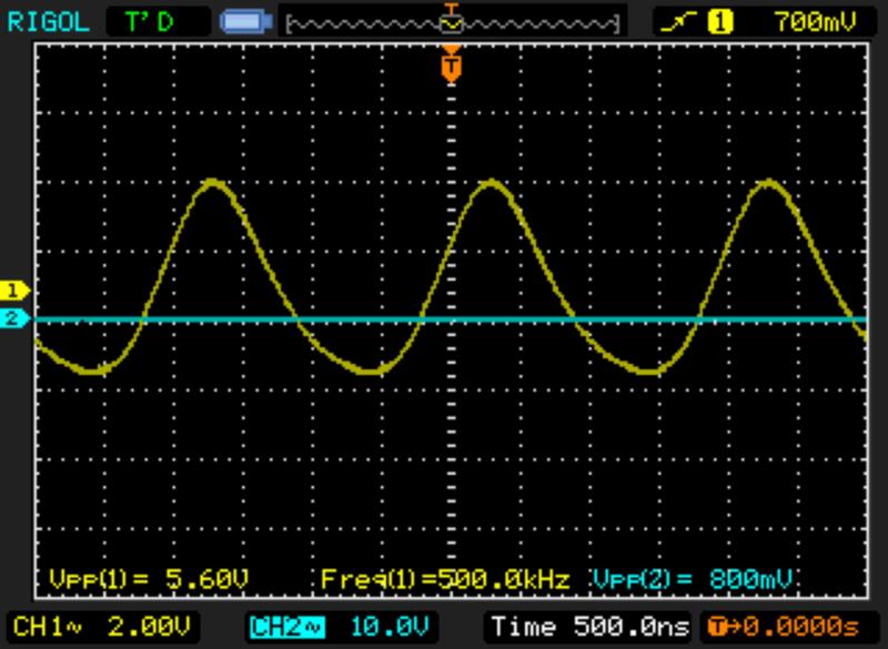
Latest Articles
Technical
Posted: 01/29/2025
Comments: 0 |
Pico Rx performance - Excellent performance on 630m WSPR
The Simple Pico Rx is my minimalist implementation of Jonathan Dawson's "Pico Rx" at 101things: https://github.com/dawsonjon/PicoRX In this basic form the receiver consists of a Quadrature Sampling Detector (QSD aka Tayloe) and the Pico2 MCU which handles all DSP functions. There are NO front-end filters, the only bandwidth limitation comes from the tracking filter... READ MORE |
Crystal Replacement
Posted: 08/226/2024
Comments: 0 |
Making SMT "no lead" parts easier to use
SMT is the future - but how can we actually use parts without leads? ... READ MORE |
|
Crystal Replacement
Posted: 02/38/2024
Comments: 0 |
How good can a crummy receiver be?
Hundreds of different simple SDR receivers have been designed around Dan Tayloe's Quadrature Sampling Detector or QSD. Mine add nothing to the state of the art, and in fact subtract things, as I like minimalist solutions and the QSD is right in that sweet spot. Following the evolution of Tayloe's design I delete the resistors in series with the sample lines for inst... READ MORE |
Technical
Posted: 02/37/2024
Comments: 0 |
What's in a number (3253)?
The FST3253 dual four-to-one mux/demux IC has long been used as a "Tayloe Detector" or QSD (and QSE) in low-cost SDRs. They provide incredible performance for such a simple circuit, converting RF to baseband IQ with low loss and the ultimate in simplicity. Unfortunately the original FST3253 part has become obsolete and while substitutes are available, this is where the... READ MORE |
Vintage Ham Radio
Posted: 02/32/2024
Comments: 0 |
The Stancor 10P Transmitter
There weren't really many commercial transmitters in the 1930s as most hams built their own. But many of the ones that were offered came from the transformer companies who had two chances to profit. First, from those who would buy the kit, and two, from those would would see it in the (free) booklets the companies provided to their distributors who would then sell the iron to ham... READ MORE |
Vintage Ham Radio
Posted: 12/355/2023
Comments: 0 |
The Care and Feeding of the EF Johnson Courier amplifier
The EF Johnson "Courier" is a grid-driven amplifier using two 811A tubes. Switching is provided for operating in either class C for CW or as a class B linear amplifier for AM or SSB. Rated power is 500 watts input for CW, 500 watts PEP input for SSB, and 200 watts input for double-sideband AM with carrier. Since all amateur power levels were meas... READ MORE |
Historic
Posted: 11/329/2023
Comments: 0 |
TV Duplexer
Some things are interesting, even if totally useless nowadays. Such is the case with the Philco 426-3034 Crossover Kit for UHF TV. What the heck is that? Well, back in the late 50s, UHF television stations operating on channels 14-83 started to appear in many areas of the US where viewers had a VHF-only TV antenna, and in many cases an externa UHF converter was... READ MORE |
Crystal Replacement
Posted: 11/327/2023
Comments: 0 |
Replacing failed crystals
For decades, quartz crystals were used everywhere a stable frequency source was needed, even in some applications that depended on overtone (harmonic) behavior into the VHF range. These crystals were less stable and more dependent on circuit parameters that fundamental types and thus more problematic. Such was the case with the 94 MHz crystal in the 2 meter converter ... READ MORE |
Historic
Posted: 11/315/2023
Comments: 0 |
My Own Ham Radio Story by W9RAN
Everyone has a story of how they got involved in ham radio - this is mine. It started much earlier, including receiving a Knight Kit Span Master shortwave radio for Christmas in about 1963, at age 12. I'll never forget the night my dad and I finished building it and I wanted to try it out. It came with a 50 ft. antenna which was still coiled up - but ... READ MORE |

Technical
Posted: 09/267/2023
Comments: 0 |
Hot to simulate vacuum tubes in LTSpice
LTSice is a powerful simulation tool that is provided free by Linear Technology Corp. It comes with a complete library of passive and common analog solid-state components but if you want to use it to simulate vacuum tubes, it doesen't work as-is. Even though triode and pentode symbols can be found in the "Misc" folder, they are just schematic symbols and... READ MORE |